Fire Alarm Circuit Diagram

Fire Alarm Circuit Diagram

Fire Alarm Circuit : Specifications

  • Audible and visual alarm output
  • Designed for quick and easy installation
  • Suitable for residential and commercial use
  • Built-in test function for maintenance checks
  • Battery backup ensures continuous operation
  • Operates on low voltage for energy efficiency
  • Compatible with smoke, heat, and flame detectors

Category: Fire Alarm System

Table of Contents

Description

The Fire Alarm Circuit is a fundamental component for fire detection, providing reliable performance and rapid response during emergencies.

Function

The Fire Alarm Circuit monitors connected detectors and triggers audible and visual alarms during a fire. It ensures quick detection and alerts building occupants, minimizing potential damage and providing time for evacuation.

General Components in a Circuit Diagram of Fire Aarm

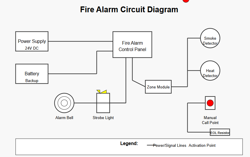
This fire alarm system circuit diagram shows the essential components of a basic fire detection and alarm system:

  1. Power Supply (24V DC) – The main power source for the system
  2. Battery Backup – Provides power during main power failures
  3. Fire Alarm Control Panel – The central unit that monitors inputs and controls outputs
  4. Detection Devices:
    • Smoke Detector – Detects smoke particles in the air
    • Heat Detector – Activates when temperature exceeds a threshold
    • Manual Call Point – For human-activated alarms in emergencies
  5. Notification Devices:
    • Alarm Bell – Audible notification
    • Strobe Light – Visual notification
  6. Zone Module – Monitors a specific area of the building
  7. End of Line (EOL) Resistor – Allows the system to monitor for wire faults

The simple fire alarm circuit diagram shows how these components are interconnected in a typical installation. The control panel receives signals from the detection devices and activates the alarm devices when a fire condition is detected.

Fire alarm circuit Diagram

5 Benefits of Fire Alarm Circuit

  1. Easy installation.
  2. Low power consumption.
  3. Fast and reliable fire alert.
  4. Supports multiple detectors.
  5. Continuous operation during power outages.

FAQ

The BC547 transistor is used in fire alarm systems as a switch that detects small electrical signals from sensors and triggers the alarm when smoke or heat is detected.

A fire alarm system is wired with:

  1. Power supply (AC with battery backup)
  2. Control panel as the central hub
  3. Initiating devices (smoke/heat detectors, pull stations) wired in parallel
  4. Notification devices (horns, strobes) on separate circuits
  5. End-of-line resistors to monitor circuit integrity
  6. Either Class A wiring (loop configuration) or Class B wiring (linear)
  7. Zone separation in larger buildings

Addressable systems use digital communication over fewer wires, with each device having a unique ID.