

Table of Contents
ToggleFire Alarm Circuit : Specifications
- Audible and visual alarm output
- Designed for quick and easy installation
- Suitable for residential and commercial use
- Built-in test function for maintenance checks
- Battery backup ensures continuous operation
- Operates on low voltage for energy efficiency
- Compatible with smoke, heat, and flame detectors
Category: Fire Alarm System
Description
The fire alarm circuit is a fundamental component for fire detection, providing reliable performance and rapid response during emergencies.
Function
The fire alarm circuit monitors connected detectors and triggers audible and visual alarms during a fire. It ensures quick detection and alerts building occupants, minimizing potential damage and providing time for evacuation.
General Components in a Circuit Diagram of Fire Aarm
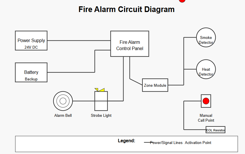
This fire alarm system circuit diagram shows the essential components of a basic fire detection and alarm system:
- Power Supply (24V DC) – The main power source for the system
- Battery Backup – Provides power during main power failures
- Fire Alarm Control Panel – The central unit that monitors inputs and controls outputs
- Detection Devices:
- Smoke Detector – Detects smoke particles in the air
- Heat Detector – Activates when temperature exceeds a threshold
- Manual Call Point – For human-activated alarms in emergencies
- Notification Devices:
- Alarm Bell – Audible notification
- Strobe Light – Visual notification
- Zone Module – Monitors a specific area of the building
- End of Line (EOL) Resistor – Allows the system to monitor for wire faults
The simple fire alarm circuit diagram shows how these components are interconnected in a typical installation. The control panel receives signals from the detection devices and activates the alarm devices when a fire condition is detected.
How a Fire Alarm Circuit Works: Step by Step
Step 1: Continuous Monitoring
The fire alarm circuit works as a continuous supervised loop. The control panel constantly sends a small monitoring current through the circuit.
Step 2: Detection of Fire
When a device such as a smoke detector, heat detector, or manual call point detects a fire condition, it changes the electrical state of the circuit loop.
Step 3: Signal Recognition by Panel
The control panel detects this change in the circuit and identifies which zone has been affected.
Step 4: Alarm Activation
Once the fire condition is confirmed, the panel immediately activates alarm devices such as bells, strobes, and sounders.
Step 5: Role of End-of-Line (EOL) Resistor
An end-of-line (EOL) resistor is installed at the end of each zone circuit to maintain a fixed resistance value, allowing the system to monitor circuit health.
Step 6: Open-Circuit Fault Detection
If a wire is cut or broken, the resistance disappears. The panel detects this and registers an open-circuit fault.
Step 7: Short-Circuit Fault Detection
If two wires touch and create a short circuit, the resistance drops to near zero. The panel identifies this as a short-circuit fault.
Step 8: Automatic Fault Monitoring
These mechanisms ensure that faults are detected automatically, even when there is no fire.
Step 9: Backup Power Activation
In case of a mains power failure, the battery backup system automatically activates within milliseconds.
Step 10: Continuous Protection
The system continues monitoring without interruption, ensuring constant safety and protection for occupants.
Types of Fire Alarm Circuits
Not all fire alarm circuits are wired the same way. The circuit topology determines how many devices can be connected, how faults are identified, and how the system scales as a building grows.
Conventional 2-wire circuit
The simplest topology. All detectors in a zone share one pair of wires. The panel knows a zone is in alarm but cannot identify which individual detector triggered it. Suited to small residential and small commercial buildings where zones are compact.
Conventional 4-wire circuit
Uses separate wiring for power and signal. Provides a cleaner signal separation and is less susceptible to interference. Common in medium-sized commercial installations.
Addressable SLC loop
Each device has a unique address and communicates its exact identity and status back to the panel independently. A single loop can carry hundreds of devices.
Because the panel knows precisely which device was activated, response time and fault diagnosis are dramatically faster.
GreenTech’s addressable fire alarm system uses this topology for commercial, industrial, and multi-floor buildings.
Wireless circuit
No physical signal wiring between devices and the panel. Each detector communicates via radio frequency.
Ideal for heritage buildings, temporary installations, or structures where cable routing is impractical. See our guide to wireless fire alarm systems for a full breakdown.
Circuit type | Device identification | Wiring complexity | Best for |
Conventional 2-wire | Zone only | Low | Homes, small offices |
Conventional 4-wire | Zone only | Medium | Medium commercial |
Addressable loop | Individual device | Medium | Large/multi-floor buildings |
Wireless | Individual device | Very low | Heritage, temporary sites |
Not sure which fire alarm circuit is right for your building?
Our engineers assess your site, occupancy type, and compliance requirements — then recommend the exact circuit design you need.

Why is the BC547 transistor used in a fire alarm system?
The BC547 is a general-purpose NPN bipolar junction transistor (BJT) that acts as an electronically controlled switch inside simple fire alarm circuits, particularly in low-cost residential and educational project designs.
A thermistor or LDR (light-dependent resistor) is the sensing element in a normal fire alarm circuit that uses the BC547.
Under normal conditions, the base of the BC547 receives insufficient current to switch the transistor on, so no current flows from collector to emitter, and the alarm remains silent.
When a fire raises the ambient temperature or smoke disturbs the sensor’s light path, the sensor’s resistance changes.
This allows enough base current to flow into the BC547, driving the transistor into saturation — its collector-to-emitter path effectively closes. Current now flows through the alarm circuit, triggering the buzzer or bell.
Why the BC547 specifically?
- Low base current requirement (typically 5 mA) — easily driven by sensor outputs
- Readily available and extremely low cost across Pakistan
- Operates reliably on 5V–9V DC supply, matching battery-operated circuits
- Short switching time means fast alarm response
It is worth noting that the BC547 is used in simple DIY and educational fire alarm circuits. Professional commercial systems use specialized control panels for fire alarms with supervised circuitry, not standalone transistor switching.
For buildings in Pakistan that require code-compliant systems, GreenTech designs installations around certified control panels rather than discrete transistor circuits.
Fire Alarm Circuit Wiring: Standards and Cable
Correct wiring is as important as correct component selection. A fire alarm circuit that uses undersized or unshielded cable may pass current under normal conditions but fail at the moment of a fire — the very scenario the system is designed to prevent.
Cable specification
Professional fire alarm installations in Pakistan use dedicated fire-rated cable, typically 2-core or 4-core screened cable with red outer sheath for easy identification.
The screening (foil or braid) reduces electromagnetic interference from nearby power cables, lighting circuits, and industrial equipment. GreenTech supplies and installs the correct fire alarm cable rated for the specific panel and detector combination in every project.
Wiring colour convention
- Red: positive supply / alarm circuit
- Black or blue: negative / return
- Green/yellow: earth/ground
- Screen drain wire: connected to earth at panel end only (one-end earthing avoids ground loops)
Separation from Power Wiring
Fire alarm cables must be segregated from mains voltage cables. Routing them in the same conduit as 220V supply wiring creates interference and, in some installations, regulatory non-compliance.
Pakistan Regulatory Requirements
Commercial buildings in Pakistan are increasingly required to comply with NFPA 72 (National Fire Alarm and Signalling Code) or BS 5839 for the design and installation of fire detection circuits.
These standards mandate supervised wiring — the end-of-line resistor configuration described above — so that any cable break is detected automatically. Understanding fire safety laws in Pakistan helps building owners confirm what their project is legally required to include.
Get your fire alarm circuit installed to NFPA 72 standard!
GreenTech’s certified technicians handle design, supply, installation, and commissioning from a single point of contact.

Common Circuit Faults and How to Identify Them
Even a correctly installed fire alarm circuit can develop faults over time due to cable damage, corrosion, moisture ingress, or incorrect modifications. The three fault types every facility manager should recognize are:
Open Circuit Fault
Cause: a wire is cut, a terminal is loose, or a detector is removed without proper isolation.
Effect: the EOL resistor is disconnected from the panel, so the panel reads infinite resistance — a fault condition. The panel logs the fault and typically shows which zone is affected.
Short Circuit Fault
Cause: Two conductors in the circuit make contact, usually due to damaged cable insulation.
Effect: resistance on the loop drops to near zero.
The panel detects this as a distinct short-circuit fault. On conventional systems, a short circuit may silence an entire zone; addressable systems use isolator modules to cut the fault and keep the rest of the loop active.
Earth Fault
Cause: a conductor makes contact with a grounded surface — a metal conduit, a structural beam, or a damp wall.
Effect: The panel detects a current path to earth and logs an earth fault. Left unresolved, earth faults can mask genuine alarm conditions.
Routine inspection and testing resolve most faults before they become critical. GreenTech recommends annual circuit verification alongside detector testing. Our fire safety equipment maintenance guide covers the full inspection schedule.
5 Benefits of Fire Alarm Circuit
- Easy installation.
- Low power consumption.
- Fast and reliable fire alert.
- Supports multiple detectors.
- Continuous operation during power outages.
Why GreenTech Solution is Pakistan's Trusted Choice for Complete Fire Protection?
- End-to-end service — GreenTech designs, installs, and maintains complete fire alarm systems, so you never have to coordinate between multiple vendors.
- NFPA 72 certified installations — Every circuit is wired and commissioned to international fire safety standards, keeping your building compliant and legally covered.
- Right system for your building — Whether it’s a 2-wire conventional circuit for a small office or a fully addressable loop for a multi-floor commercial tower, we recommend what your site actually needs.
- Trusted brands, all under one roof — We supply and install Honeywell detectors, Esser control modules, fire-rated cables, and manual call points — no third-party sourcing delays.
- Local expertise across Pakistan — From Rawalpindi to Karachi, our certified engineers understand local building requirements and regulatory expectations on the ground.


Frequently Asked Questions
A fire alarm circuit diagram shows how detectors, control panels, and alarms are connected. At GreenTech, we design accurate and efficient circuit layouts for reliable fire detection systems.
Our process includes site analysis, component selection, wiring design, and system integration. We ensure every circuit meets safety standards and performs efficiently during emergencies.
A complete system includes smoke/heat detectors, control panels, alarm sounders, wiring, and communication devices—all supplied and installed by GreenTech.
For safety and compliance, professional installation is highly recommended. GreenTech provides certified installation services to ensure your system works flawlessly.
Ready to secure your building with the right fire protection system?
Understanding how fire alarm circuits work is the first step — but getting the installation right is what actually keeps people safe. Whether you need a conventional 2-wire system for a small office or a fully addressable loop for a multi-floor commercial building, GreenTech’s engineers handle everything from site assessment to commissioning, in full compliance with NFPA 72.